
Commercial mobile coverage and DAS
We specialise in the end-to-end design, installation and maintenance of mobile repeater distributed antenna systems (DAS), delivering high-performance, legally compliant coverage for commercial, industrial and public infrastructure across Australia and New Zealand.
What a DAS changes in a large retail store
Glazing, concrete and steel weaken mobile signal as it travels into a building. Drag across an illustrative retail floor plan to compare the existing signal with coverage from an engineered DAS, shown as RSRP in dBm on the shop floor, the undercroft car park and the plant level.
Illustrative retail floor plan. Pre- and post-installation RSRP, simulated.

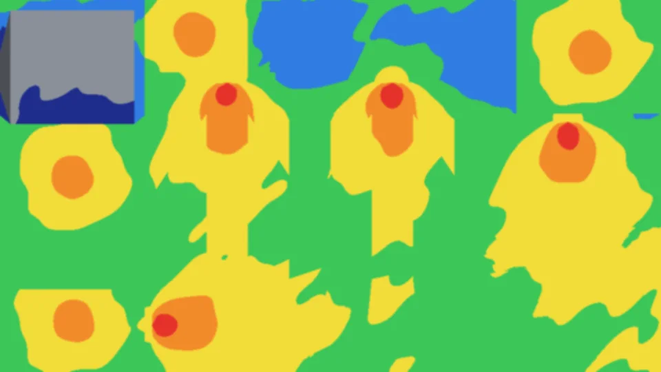

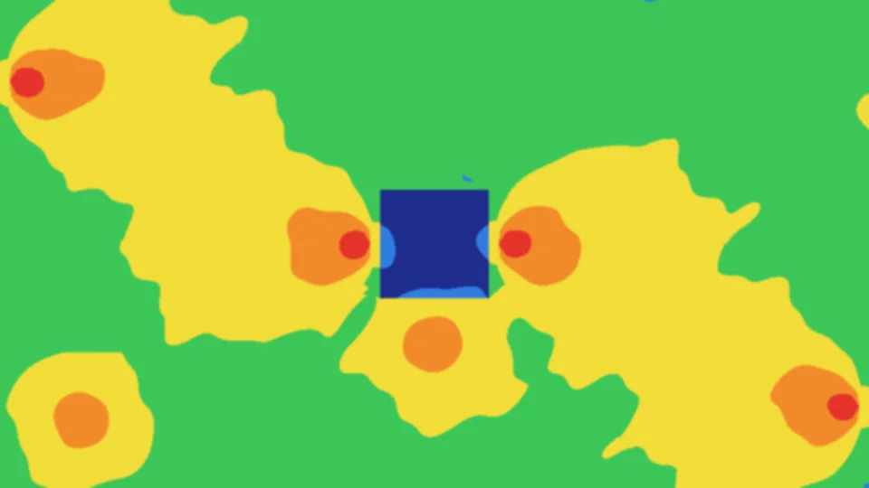


RSRP colour legend
Excellent
- ≥ −60 dBm
- −70 to −60 dBm
- −80 to −70 dBm
Good
- −90 to −80 dBm
- −100 to −90 dBm
Poor
- −110 to −100 dBm
Unusable
- −120 to −110 dBm
- −150 to −120 dBm
- < −150 dBm
- Ceiling dome antenna
- High-gain panel antenna and its main beam
- Repeater hub
- Cable path (indicative)
- Riser to roof donor antennas
| Area | Existing | With DAS |
|---|---|---|
| Shopfront and checkouts | −90 | −82 |
| Shopping aisles | −107 | −80 |
| Fresh food | −95 | −76 |
| Back of house | −120 | −78 |
| Cool rooms | −124 | −111 |
| Offices and comms | −102 | −85 |
| Specialty tenancy | −94 | −80 |
Tilt-up concrete walls, a glazed shopfront, metal shelving, cool rooms and back of house. High-gain panel antennas at the edge of the sales floor aim down the aisles and along the checkouts; ceiling domes cover back of house, offices and the specialty tenancy.
| Area | Existing | With DAS |
|---|---|---|
| Near the ramp | −99 | −84 |
| Parking aisles | −133 | −77 |
| Lift lobby | −135 | −74 |
| Plant room | −141 | −77 |
| Lifts and stairs | −146 | −103 |
Below the store: concrete slab and walls, with outside signal entering only at the vehicle ramp. Four panel antennas throw coverage the length of the parking aisles; domes cover the lift lobby and plant room.
| Area | Existing | With DAS |
|---|---|---|
| Plant room | −100 | −77 |
| Staff room | −98 | −77 |
| Offices | −94 | −77 |
| Training room | −91 | −76 |
A small first floor above back of house. The rest of the footprint is roof.
Signal strength is one measure. Call quality and data speed also depend on interference (SINR), network capacity and the number of users, so a strong RSRP alone does not guarantee service. Cool rooms and lift shafts usually need their own antennas, which are designed separately.
Coverage target. Proeye designs to RSRP better than −95 dBm in the areas that need service. In this simulation every area meets it except the cool rooms and the lift shafts.
Designed, then measured
The heatmap above is a simulation. This is what happened in a real large warehouse store in Victoria, upgraded to CEL-FI QUATRA 4000e with panel antennas in 2026. We predicted coverage at design, measured the signal before the upgrade, and surveyed every carrier after commissioning. See the project.
27 of 27 test areas better than Proeye's −95 dBm coverage target: nine for each of Optus, Telstra and Vodafone. The survey report's own acceptance criterion was −105 dBm, which every area also passed.
As-built survey by test area (dBm)
| Test area 5: −76.5 | Test area 6: −79.5 | Test area 7: −81.7 |
| Test area 9: −88.5 | Test area 10: −83 | Test area 11: −85.8 |
| Test area 13: −77 | Test area 14: −88.5 | Test area 15: −84 |
| Test area 5: −70.5 | Test area 6: −75.5 | Test area 7: −79.7 |
| Test area 9: −81 | Test area 10: −77 | Test area 11: −78.8 |
| Test area 13: −69 | Test area 14: −83.5 | Test area 15: −79.5 |
| Test area 5: −70 | Test area 6: −75 | Test area 7: −76 |
| Test area 9: −81 | Test area 10: −80 | Test area 11: −78.6 |
| Test area 13: −67 | Test area 14: −79 | Test area 15: −74 |
Colours follow the RSRP legend above. The grid shows the survey's test areas, not the store layout.
Measured data from Proeye's own reports. Before: CEL-FI COMPASS meter, one point in the middle of the store, strongest cell per carrier. After: Nextivity WAVE signal survey, nine test areas on the sales floor, average of the strongest readings in each area. The two methods differ, so compare the trend rather than single numbers. The prediction comes from Proeye's design drawing. The client and site are not named.
Choosing the donor antenna
Every DAS starts with a clean signal from outside. The donor antenna on the roof decides which cell site the building listens to, so we choose its type and aim from measurements of each carrier on site.
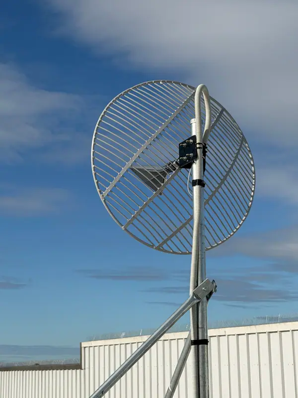
Ultra-wideband parabolic grid
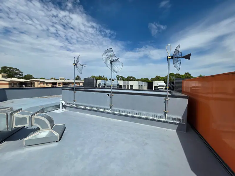
A narrow beam concentrates gain on one chosen cell site and gives it a strong lead over neighbouring sites. This is our usual donor where the serving site is distant or several sites compete.
- Frequency
- 600–6500 MHz
- Gain (typical)
- 15 / 20 / 23 dBi (low / mid / high band)
- 3 dB beamwidth
- About 20° / 12° / 7°
- Front to back
- 18–24 dB
High-gain SISO panel
A wider beam with moderate gain. It suits a donor where the serving site is closer, or a coverage antenna for large open areas such as warehouses and car parks.
- Frequency
- 698–960 and 1710–3800 MHz
- Gain
- 11.5–12.5 dBi
- Horizontal beamwidth
- 65° / 55°
- Front to back
- 15 / 20 dB
Omni ceiling antenna
Low gain in every direction. It is the right choice for spreading signal indoors from the ceiling, but as a donor it would hear every nearby site equally and give none of them a lead.
- Frequency
- 698–3800 MHz
- Gain
- 3 / 5 dBi
- Horizontal beamwidth
- 360°
- Use
- Indoor coverage antenna
Figures are from Proeye's antenna data sheets for its ultra-wideband grid, high-gain SISO panel and 5G dome antennas. Donor choice is confirmed by measuring each carrier's signal on the roof.
Inside a CEL‑FI system
For larger buildings we design active DAS around CEL-FI QUATRA 4000e. Step through how the signal travels from the roof to every floor, or select any part of the drawing.
Follow the signal
Donor antennas receive each carrier
Parabolic grid antennas on the roof are aimed at selected cell sites, one per carrier. Each donor line passes through surge protection bonded to the building earth before it drops down the riser.
The Network Unit processes the signal
The Network Unit (NU) has four donor ports and handles up to four operators. It digitises and filters the carrier signals, with up to 100 dB of system gain. A power divider lets one carrier use two ports, and a UPS keeps the NU powered.
Category cable carries it to each floor
Each Coverage Unit (CU) connects to the NU with two category cables, which carry the signal and power the CU over Ethernet (PoE+). One NU serves up to six CUs, each up to 100 m away, or 200 m with a range extender.
In a lift, a CU is fixed to the lift car. Its two category cables travel with the car up and down the shaft, and a coverage antenna inside the car keeps phones connected as it stops at each floor.
Indoor antennas cover each area
From each CU, 50-ohm coaxial cable and directional couplers share the signal between ceiling dome antennas. Phones connect to these antennas, and their uplink travels the same path back to the network.
The system is managed remotely
Nextivity's WAVE Portal monitors and configures the system from the cloud. In our designs, a modem with VPN access also gives our team a secure path for remote support.
Simplified from Proeye's CEL-FI QUATRA 4000e design drawings. Figures are from Nextivity's QUATRA 4000e data sheet. Antenna counts, cable runs and equipment locations are designed for each building.
Follow the signal
Donor antennas receive each carrier
Parabolic grid antennas on the roof are aimed at selected cell sites, one per carrier. Each donor line passes through surge protection bonded to the building earth.
Power dividers share each carrier between floors
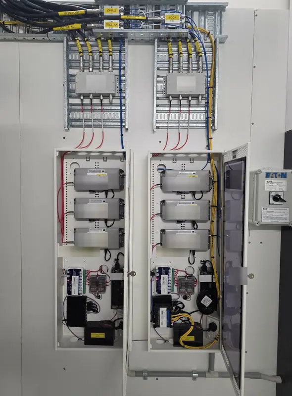
A power divider on each donor line sends that carrier down the riser to every floor. Each hub receives Optus, Vodafone and Telstra on separate, labelled lines.
A repeater hub on each floor
Each floor has a pre-built Proeye repeater hub holding one CEL-FI GO G41 per carrier. A G41 serves one operator on up to two bands, with up to 100 dB of system gain and 20 dBm of downlink output. Hubs are built and tested before they reach site.
Four coverage cables from every hub
The hub sits in the middle of the floor and runs four 50-ohm coaxial cables, two to each side. On each side, the first cable feeds four coverage antennas close to the hub, and the second runs past them to four more further out. Phones connect to these antennas, and their uplink travels the same path back to the network.
The hubs are managed remotely
In a managed system, a modem in one hub connects it for remote support, and category cable lets the other hubs share it. An IP relay can power-cycle modules from a web browser, and Nextivity's WAVE Portal monitors each G41.
Simplified from Proeye's repeater hub reference designs and multi-floor hub installations. Figures are from Nextivity's CEL-FI GO G41 data sheet. Hub numbers, antennas and cable runs are designed for each building; a single-carrier site needs one G41 per hub.
Our DAS installation process
Whether you are dealing with black spots, weak signal or unreliable data, our tailored solutions deliver seamless voice and data connectivity across your premises.
Desktop analysis & signal survey
A free initial desktop analysis, then RF and cellular measurements on site with professional-grade tools to map coverage challenges and identify signal sources.
System design & engineering
Custom DAS designs using CEL-FI repeater equipment listed for the carriers involved, aligned with building layout, materials and usage patterns.
Compliance & carrier coordination
Each carrier's permission is part of the project, and every system is installed to ACMA requirements, for legal operation with minimal risk of interference. Repeaters and the law.
Professional installation
Turnkey and scalable managed installations by certified technicians experienced across aged care, retail, healthcare, commercial and construction.
Commissioning, testing & reporting
Post-installation testing, signal validation and handover documentation, so your system performs reliably in real-world conditions.
Maintenance and support after handover
We understand the importance of system uptime and reliability. Support is matched to how critical coverage is to your site.
Remote management & break-fix
Remote monitoring tools and diagnostics to detect and address issues before they affect users.
On-site technician break-fix
Access to our team for troubleshooting, on-site support and fast response to service disruptions.
Maintenance plans
Routine inspection and performance tuning to keep signal strength optimal and extend system life.
Remote diagnostics & reporting
Monitoring and reporting so you can see how the system is performing over time.
On-call technical support
Direct access to the people who designed and installed your system.
Upgrades & optimisation
As technology and coverage requirements evolve, we assess, upgrade or expand your DAS to adapt for future growth.
Permanent and temporary systems
Permanent coverage
Enhance in-building mobile coverage for staff, clients and visitors across multi-level and large building enclosures.
- Hospitals and aged care. Consistent connectivity for medical staff, patients, emergency responders and IoT-based medical equipment in signal-challenged areas.
- Retail stores. Better mobile service for customers and POS systems in shopping complexes and standalone stores.
- Hotels and venues. Coverage for guests and staff across guest floors, function rooms, back of house and car parks. Hotels and venues.
- Data centres. Coverage through data halls, plant rooms and secure zones, across multiple levels and buildings. Data centres.
- Logistics and freight. Coverage for operational continuity, logistics tracking and team communications in buildings with thick walls, metal structures or large coverage zones.
Temporary coverage, on short-term lease or hire
- Events and functions. Reliable voice and data at conferences, exhibitions and large corporate gatherings, especially in venues with poor indoor reception.
- Construction sites. Site management, safety systems and communications for new builds or remote work sites with poor signal.
- Healthcare relocations. Seamless coverage during temporary relocations, renovations or expansions within hospitals, aged care homes and clinics.
- Moving premises. Immediate mobile signal support during the move into new premises or while infrastructure upgrades are underway.
- Outages and delays. Bridge the gap during carrier outages, cabling issues or network upgrade delays to avoid disruption.
Where coverage typically fails
These are the spaces we are most often asked to fix.
- Aged care
- Basements
- Loading areas
- Gymnasiums & pools
- Retail stores
- Office buildings
- Warehouses
- Construction & mining sites
- In lifts
- Clinics & hospitals
Why choose Proeye
- Certified CEL-FI and DAS designers and installers
- Projects involving Telstra, Optus and Vodafone, with each carrier's requirements confirmed per site
- Detailed signal reporting and project documentation
- End-to-end project management from consultation to handover
- A Melbourne team delivering projects across Australia and New Zealand
A mobile repeater extends available cellular signal into a building. It does not add capacity at the serving base station, and performance depends on donor signal, building conditions and the mobile network.
In-lift coverage
A lift car is a steel box moving inside a concrete shaft, so phones often lose signal the moment the doors close.
That matters for passengers mid-call, for staff and contractors who rely on their phones between floors, and for lift emergency phones and alarm devices that use the mobile network. We include lift shafts in the survey and design, so coverage continues between floors rather than stopping at the lift lobby.
- Surveyed with the rest of the building, inside the car and at each landing.
- Antennas in the lift shaft or on the lift car, fed from the building's repeater DAS.
- Work in the shaft coordinated with your lift contractor, who controls access and isolation.
- Call tests in the moving car between floors at handover.
- Suitable for new and existing buildings, with CEL-FI G41 or CEL-FI QUATRA systems depending on the building.
A lift car in Victoria
In this CEL-FI QUATRA 4000e system, a Coverage Unit rides on top of the lift car, mounted on a chequer-plate bracket inside the shaft and cabled back to the Network Unit in the communications cabinet. A flush black dome antenna in the car ceiling carries the signal to passengers inside the car.
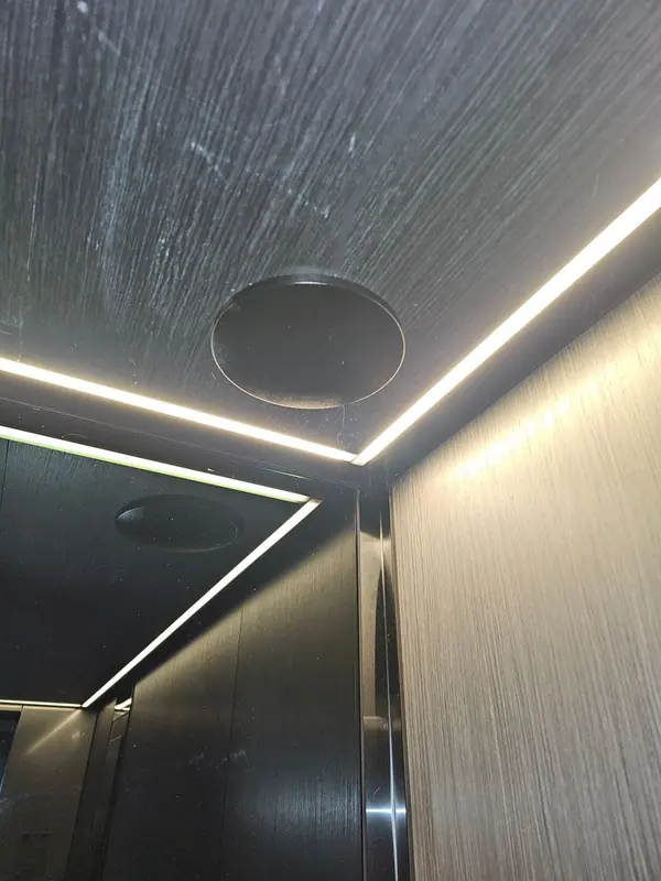
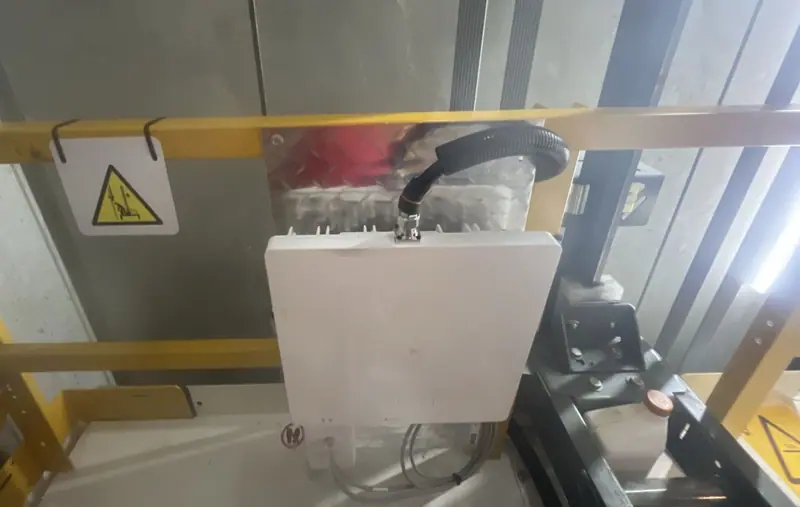
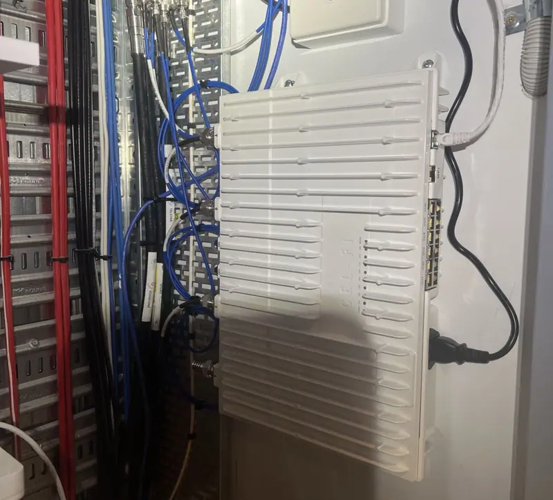
The dome antenna in the lift car ceiling, the QUATRA Coverage Unit on the car top, and the Network Unit in the communications cabinet. Address stamps are cropped out. See the project
What you receive
Every coverage project is documented from the first survey to handover.
- Signal survey findings. Measured indoor and outdoor signal for each carrier, with the areas that need coverage.
- System design drawing. Equipment, donor and indoor antenna locations and cabling for the building.
- Predicted coverage drawing. The coverage the design is expected to deliver, area by area.
- Compliance and carrier coordination. The carriers' requirements confirmed for the site, and installation to ACMA requirements.
- Commissioning and handover documentation. Signal validation and test results from the completed system.
Nextivity Elite System Integrator, certified for CEL-FI design, installation and maintenance. See our credentials






From our projects
Recent mobile coverage installations in retail and aged care. Client names are withheld. Read more about retail and warehouses and aged care and health.
Ready for a quotation?
Send the building details and plans through our quote request form, or start with a free initial desktop analysis.
Equipment for your DAS
Choosing a CEL-FI system
When to use G41 repeater hubs or QUATRA, and which models are listed for which carriers.
CEL-FI & QUATRA systemsRepeater hubs & CEL-FI QUATRA
Managed G41 repeater hubs, QUATRA 4000e and QUATRA EVO active DAS.
Compare systemsDAS & telecommunications components
Proeye dome, panel and parabolic antennas, couplers, connectors and mounting hardware.
Browse componentsFind out what is blocking your signal
Start with a free initial desktop analysis. An onsite signal survey then shows where coverage fails and what it will take to fix it.